Introduction

The original autolevel sensor that came with my printer was an inductive kind. Aside from the fact this was less than ideal to set up, there were some fundamental points I didn’t understand about bed levelling. One of these, is that unless you store the bed levelling settings, then tell the firmware to retrieve them after homing, no matter how well the sensor is setup, it’s not going to produce the outcome you think.
First Attempt in Learning (FAIL)
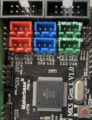
One of the biggest problems I encountered early on when trying to install and use the auto-level sensor is the heads crashing into the bed. I got so fed up with this that I moved the sensor off the z-min plug, installed an endstop switch and ran the sensor on the z-max plug. This configuration might save you a lot of pain and grief as well.
BLTouch Installation

As you can see I’ve got a Frankenstein bracket that’s made up of two metal strips with holes drilled for adjustment. I’d suggest a slot in one and holes in the other to allow even finer adjustment.
There are plenty of articles around about the wiring, and it will be different for the type of mainboard you have. In essence however there are three wires that go to a servo plug, and two that will go to the z-min/z-max plug depending on which one you’re choosing to use.
So far as the servo goes, there’s a (+) (gnd) and (signal) wire. Get a wiring diagram of your mainboard, understand which of these pins are where, and connect up the servo plug. It’s assumed that you’ll be using servo plug 0.
Now the remaining two wires need to go onto the (gnd) and (signal) of the z-min/z-max plug. Most articles about set up talk about z-min, so from here on in, I’m going to talk about configuration with the sensor on the z-max plug, and an endstop on the z-min plug.
zmin-endstop and zmax-probe
This configuration leverages an endstop switch as a fail safe in case the z-probe fails for some reason. I’ve had both the inductive and BLTouch probes fail which resulted in head crashes without the endstop on z-min.
The ideal position for the endstop is just below where the hotends touch the bed. This ensures that G28 homing works correctly but also prevents the endstop kicking in before the z-probe can do it’s thing.
MKS Gen L V1.0 Marlin 1.1.x Configuration
//===========================================================================
//============================== Endstop Settings ===========================
//===========================================================================

#define USE_XMIN_PLUG
#define USE_YMIN_PLUG
#define USE_ZMIN_PLUG
//#define USE_XMAX_PLUG
//#define USE_YMAX_PLUG
#define USE_ZMAX_PLUG

#define X_MIN_ENDSTOP_INVERTING false // set to true to invert the logic of the endstop.
#define Y_MIN_ENDSTOP_INVERTING false // set to true to invert the logic of the endstop.
#define Z_MIN_ENDSTOP_INVERTING false// set to true to invert the logic of the endstop.
#define X_MAX_ENDSTOP_INVERTING false // set to true to invert the logic of the endstop.
#define Y_MAX_ENDSTOP_INVERTING false // set to true to invert the logic of the endstop.
#define Z_MAX_ENDSTOP_INVERTING false // set to true to invert the logic of the endstop.

//===========================================================================
//============================== Probe Settings ===========================
//===========================================================================

#define Z_MIN_PROBE_ENDSTOP
//#define Z_MIN_PROBE_PIN 19 // Defaults to z-max plug anyway which is pin D19

#define Z_ENDSTOP_SERVO_NR 0 // Assumes BLTouch plugged into Servo 0 plug

#define BLTOUCH
#if ENABLED(BLTOUCH)
  #define BLTOUCH_DELAY 300   // Marlin 2.0.x doesn't allow anything less than this so 300ms is a good value IMO
#endif

#define X_PROBE_OFFSET_FROM_EXTRUDER 42  // X offset: -left  +right  [of the nozzle]
#define Y_PROBE_OFFSET_FROM_EXTRUDER 5  // Y offset: -front +behind [the nozzle]
#define Z_PROBE_OFFSET_FROM_EXTRUDER 0    // Z offset: -below +above  [the nozzle]

#define Z_CLEARANCE_DEPLOY_PROBE   10 // Z Clearance for Deploy/Stow
#define Z_CLEARANCE_BETWEEN_PROBES  5 // Z Clearance between probe points (5 is too low in Marlin 2.0.x)

//===========================================================================
//============================== Auto Level Settings ===========================
//===========================================================================

#define AUTO_BED_LEVELING_BILINEAR

// Set the number of grid points per dimension.
#define GRID_MAX_POINTS_X 5
#define GRID_MAX_POINTS_Y GRID_MAX_POINTS_X

// The Z probe minimum outer margin (to validate G29 parameters).
#define MIN_PROBE_EDGE 10

//===========================================================================
//============================== Other Settings ===========================
//===========================================================================

#define EEPROM_SETTINGS // Enable for M500 and M501 commands
#define EEPROM_CHITCHAT   // Give feedback on EEPROM commands. Disable to save PROGMEM.

#define NUM_SERVOS 3 // Servo index starts with 0 for M280 command
Key points
The endstop settings define what plugs are used, and what the endstop signal means. Inverting false means the switch is normally open. A closed state means it’s triggered. You can test your endstops by running M119; which will report their states.
In the probe settings, this is defining what signal pin the trigger is on (D19 in this case) and which servo plug. In Marlin 1.1.4 - 1.1.9 the default plug when #define Z_MIN_PROBE_ENDSTOP is set, is the z-max plug.
The PROBE_OFFSET_FROM_EXTRUDER settings are important for making sure the probe doesn’t go off the edge of the bed. Along with the MIN_PROBE_EDGE it defines how far from the edge the probe will go. If you’re unsure, set a large margin and reduce it down. On my printer the probe can’t reach the far side of the bed because it’s beyond the x-axis travel range. My bed is 310mm wide, the probe is 42mm from the hotend. The furtherest my head can travel is 260mm. Therefore I need a margin of 80 to be on the safe side. That puts the rightmost probe point at 20mm in from the right hand edge.
To get the z-offset correct, pay attention to probe calibration lower down.
EEPROM_SETTINGS need to be enabled to store the bed levelling settings once probing is complete.
The servo plugs need to be enabled. NUM_SERVOS 3.
MKS Gen L V1.0 Marlin 2.0.x Configuration
The main difference between Marlin v1.1 and v2.0 is that some settings have been discontinued. All the endstop settings for v2.0 are the same as v1.1.
// #define Z_MIN_PROBE_ENDSTOP <--- Discontinued in v2.0
#define Z_MIN_PROBE_PIN 19 // <--- Just define this instead in v2.0
The next settings are important to get right in v2.0 otherwise you might encounter “Probing failed” errors:
#define Z_CLEARANCE_DEPLOY_PROBE   10 // Z Clearance for Deploy/Stow
#define Z_CLEARANCE_BETWEEN_PROBES  10 // Z Clearance between probe points
#define Z_CLEARANCE_MULTI_PROBE     10 // Z Clearance between multiple probes
#define Z_AFTER_PROBING           10 // Z position after probing is done

#define Z_PROBE_LOW_POINT          -2 // Farthest distance below the trigger-point to go before stopping

// For M851 give a range for adjusting the Z probe offset
#define Z_PROBE_OFFSET_RANGE_MIN -20
#define Z_PROBE_OFFSET_RANGE_MAX 20
Note the following is new in v2.0
// Most probes should stay away from the edges of the bed, but
// with NOZZLE_AS_PROBE this can be negative for a wider probing area.
#define PROBING_MARGIN 80
The following is a great improvement in 2.0. I’m not sure whether 1.1.x had this feature or not:
/**
 * Normally G28 leaves leveling disabled on completion. Enable
 * this option to have G28 restore the prior leveling state.
 */
#define RESTORE_LEVELING_AFTER_G28
Probe Testing
Once the probe is installed and the firmware changes are made, you can manually test the probe before attempting to auto-level.
The commands required are:
M280 P0 S10; Deploy the probe (pin down)
M280 P0 S160; Reset probe trigger/alarm (flashing LED)
M280 P0 S90; Stow the probe (pin up)

M280 P0 S120; Probe self test (pin deploys and retracts continuous)
M280 P0 160; Stop self test
Probe Calibration
I’ve seen some articles talking about hex nut adjustment. At the top of the sensor is a fine hex nut to adjust the trigger point. On the particular sensor I have, this just results in an error. The most reliable method to calibrate the probe in my experience is as follows:
- Move the z-axis to G1 Z10 with absolute positioning.
- Deploy the probe with M280 P0 S10;
- Lower the z-axis 1mm at a time until the probe triggers.
- Raise the z-axis by 1mm, and reset the probe trigger M280 P0 S160;
- Lower the z-axis 0.1mm at a time until the probe triggers.
- Reset the probe trigger M280 P0 S160;
- Stow the probe if it isn’t already after the reset M280 P0 S90;
- Zero the Z reading in your software so Z=0
- Lower the z-axis by 1/0.1mm at a time until the hotend just touches the bed and a 0.2mm shim (or piece of paper) slides under the hotend with only sligh resistance.
- Whatever the Z is reading, this is your probe z-offset EG: -0.50.
Store the probe z-offset setting:
 M851 Z=-0.50; Set the probe z-offset (Z reading from last step)
 M500; // Store this setting
 M501; // Display current settings to confirm correct value
Now your probe is calibrated, you can auto level your bed.