Introduction

There is an abundant amount of information on the net about auto bed levelling and how it works. In spite of all this it still tends to be a dark art that’s actually far easier than experiences might have suggested.
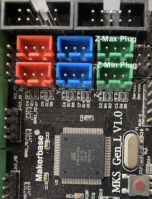
It took me a very long time to master the art of auto-levelling, mainly due to the plethora of misinformation and vague descriptions that miss important points and detail. This is further complicated by the slightly non-standard set up that I have. Many people put their sensor on the z-min plug. I’ve got an endstop on this and use the probe on the z-max plug.
Bed Levelling Demystification
Of all the problems that beset me the most, it was understanding exactly what the probe z-offset needed to be, and it’s relationship to the actual mesh itself when using the bi-linear setting in the firmware.
The first probe I tried was an inductive probe that I carefully set up so that it triggered when the hotends are just touching the bed with a slither of space measured with a shim.
When it comes to the BLTouch, there’s a lot of focus on having the height of the sensor correct. This almost takes more time and effort than manually leveling the bed!
The fact is, once you understand how the z-offset and mesh measurements work together in relation to the hotends, getting the sensor correct is surprisingly simple.
Painless AutoBed Levelling
The first thing you need to do is create a bracket for your sensor that has plenty of adjustment. Precise height isn’t necessary. Being able to adjust the sensor is important.
I have a z-min endstop as a failsafe because early on with the inductive probe, I had far too many bed crashes before I could cut the power. My BLTouch is set up on the z-max plug which is enabled in the firmware. My z-min endstop is just below the bed. The hotend can push down on the bed springs, but the endstop prevents the heads crashing any further into the bed.
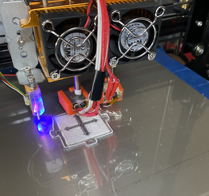
What you’re aiming for with the sensor is a height where the BLTouch will trigger when it’s lowered, before the z-min endstop kicks in, or the hotends touch the bed. You want the BLTouch positioned so that when the pin is up, it clears your build nicely.
The trick now is to get the z-offset precisely. To do so, use the following process:
G28; Home the printhead
G90; Use absolute positioning
G1 Z10; Move the z-axis 10mm above the print bed
M280 P0 S10; Push the BLTouch Z-Probe pin down
Now use your machine control panel to lower the z-axis until the probe triggers. The probe pin will pull up into the sensor, and the trigger LED will start flashing. When this happens, reset the alarm:
M280 P0 S160; Clear z-probe triggered state
Raise the z-axis by 1mm, and push the pin back down
M280 P0 S10; Push the BLTouch Z-Probe pin down
If the probe triggers immediately, reset the alarm with M280 P0 S160; raise the z-axis by another 1mm and drop the pin.
Now use the 0.1mm jog control to move the z-axis down until the pin triggers. You will now have a very accurate point at which your z-probe triggers. Reset the probe trigger state.
M280 P0 S160; Clear z-probe triggered state
In your software zero the z axis. We will now measure what the z-offset needs to be in your firmware/settings.
Lower the z-axis by 0.1mm increments until the hotends touch the bed but a sheet of paper or measuring shim fits and moves between the hotend and the bed. If you want to get fancy you can use a set of automotive feeler gauges. The feeler gauge I have is 0.20mm.
Your z-axis now has the z-offset your probe requires. The key point to note is that you’re setting the difference between the probe’s trigger height and your hotends. In my case it’s -0.50. To add it into the firmware for bed-levelling I do the following:
M851 Z-0.5; Set the probe z-offset to -0.50mm from the hotend
M500; Store the setting in EEPROM memory
M501; Confirm the setting is correctly saved
Now it’s important to perform the actual bed levelling.
G28; Home the printhead
G29; Perform bed Levelling
M500; Store the new bed level values
Test your new settings with a print. If the heads are slightly too high, the negative value needs to increase. EG: My -0.50 would be -0.60, -0.70 etc.
If the extruder is clicking when you’re doing the first layer, it comes out looking transparent or thin, the head is too close to the bed and needs to be raised. The negative value needs to decrease. EG: My -0.50 would be -0.40, -0.30 etc or even go into the positives.